Riser Irrigation Automation
 ACMA Verified
This product meets ACMA's rules and regulations https://www.acma.gov.au/
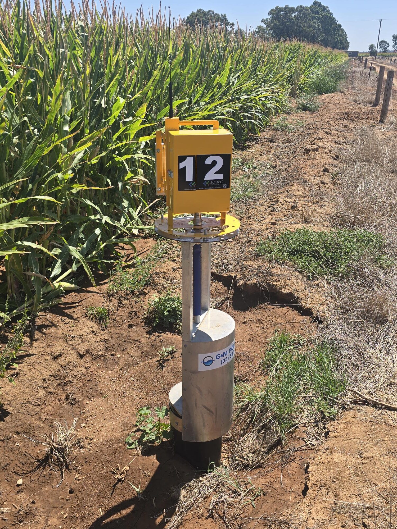
The MAC Systems Riser automation system has been designed as a fixed or portable solution for automation of Riser outlets. The design of our units allows for ease of movement, providing a portable solution for irrigation automation. Our gateway unit, which communicates with field control sites are generally installed at pump locations, where the control and monitoring of the pump can be incorporated into irrigation schedules. Web access to the system allows irrigation schedules to be monitored and adjusted and provides live data of the system and progress of the schedule. Alerts are generated should there be any issues with units with auto-skipping function.
